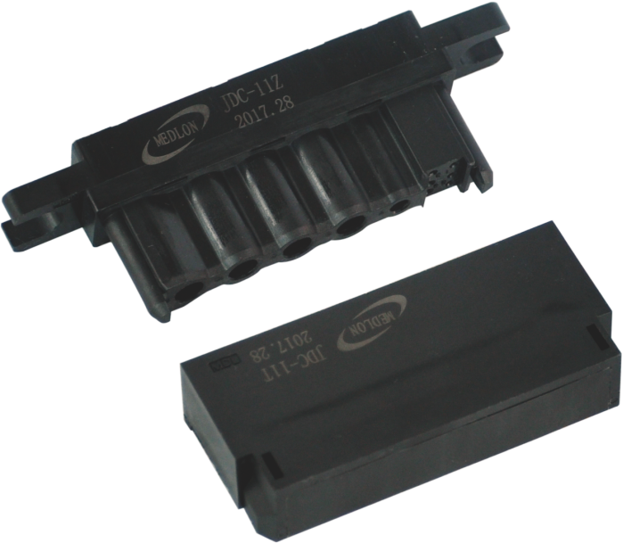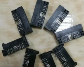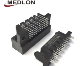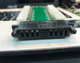


feature:
Input voltage: maximum 220V, minimum 110V
Output voltage: generally 5V or 12V
Input current: Varies according to output voltage and load power
Output power: depends on load capacity and output voltage
Working frequency: generally 50Hz or 60Hz

Advantage:
1. Versatility: Combination AC-DC and split power options are available, and the module can be configured to fit most designs
2. Convenient and flexible: easy to maintain and replace.
3. Safe and reliable: waterproof, dustproof and durable,
4. Quick connection: plug-in connection, can be quickly connected and disconnected, convenient for daily use
5. Multiple interface options: such as circular connectors, square connectors, threaded connectors, etc.
Specifications
| Component Type | circuit board power connector |
| Gender | Header/Receptacle |
| Header Pin Pattern (Left to Right) | Power/Signal |
| Number of Contacts (Power) | 4 |
| Number of Rows (Power) | 1 |
| Number of Contacts (Signal) | $keyworrd{12} |
| Number of Rows (Signal) | 9 |
| Termination Style | Solder To Board |
| Orientation | Right Angle |
| Pitch (Power) | 6.35mm (0.250in) |
| Pitch Signal) | 2.54mm (0.100in) |
| Current Rating | $keyworrd{13}A max. for One Powered Contact |
| Resistance (Power Contact) | Maximum for mated pair is 2mΩ |
| Resistance (Signal Contact) | Maximum for mated pair is 20mΩ |
| Dielectric Withstanding Voltage | $keyworrd{14}V DC for power ; $keyworrd{15}V DC for signal contacts |
| Durability (Mating cycles) | $keyworrd{16} Mating Cycles |
| Operating Temperature Range | -$keyworrd{13}°C to +125°C |
| Material Housing | PPA, glass fiber reinforce, UL94V-0 |
| Plating Contact area | 0.76μm (29.921μin) Gold |
| ail Plating (Signal) | 1.98μm (78μin) Tin |
| Tail Plating (Power) | 1.98μm (78μin) Tin |
| Guide Feature | Guide Pin Pocket |
| Packaging | Cartons or Tray |


1.Is there a maximum distance that a circuit board power connector can cover?
circuit board power connector is not a product only, but also can help you comes to money-making. The maximum distance that a power connector can cover depends on the type of connector and the power requirements of the device. Generally, the maximum distance for a power connector is determined by the voltage and current requirements of the device, as well as the type of cable used. For example, a USB cable can typically carry up to 5 volts and 1.5 amps over a distance of up to 5 meters (16 feet).
2.Are there any special tools or techniques required for installing a circuit board power connector?
Our circuit board power connector products undergo strict quality control to ensure customer satisfaction. Yes, special tools and techniques are required for installing a power connector. Depending on the type of power connector, you may need a crimping tool, soldering iron, wire strippers, and/or heat shrink tubing. Additionally, you may need to use specific techniques such as soldering, crimping, and/or heat shrinking to ensure a secure connection.
3.What are the main safety features of a circuit board power connector?
We focus on innovation and continuous improvement to maintain a competitive advantage. 1. Insulation: Power connectors should be insulated to prevent electric shock and short circuits. 2. Grounding: Power connectors should be grounded to protect against electric shock and reduce the risk of fire. 3. Overload Protection: Power connectors should be designed to prevent overloads and protect against damage to the device. 4. Overvoltage Protection: Power connectors should be designed to prevent overvoltage and protect against damage to the device. 5. Short Circuit Protection: Power connectors should be designed to prevent short circuits and protect against damage to the device. 6. Surge Protection: Power connectors should be designed to protect against power surges and protect against damage to the device.

4.How does impedance affect the performance of a circuit board power connector?
As one of the circuit board power connector market leaders, we are known for innovation and reliability. Impedance affects the performance of a power connector by limiting the amount of current that can flow through the connector. If the impedance is too high, the connector will not be able to handle the amount of current needed to power the device. If the impedance is too low, the connector will be overloaded and may cause damage to the device.
5.About circuit board power connector production capacity
The production capacity of power connectors depends on the type of connector and the manufacturer. Generally, the production capacity of power connectors is determined by the number of machines and the number of workers available. The production capacity of a single machine is usually limited to a few thousand pieces per day. However, with the help of automation, the production capacity of a single machine can be increased to several hundred thousand pieces per day.
6.What are the advantages of using a circuit board power connector instead of a wire-to-wire connection?
Our products & services cover a wide range of areas and meet the needs of different fields. 1. Power connectors provide a secure and reliable connection that is less prone to accidental disconnection. 2. Power connectors are easier to install and require less time and effort than wire-to-wire connections. 3. Power connectors are more resistant to vibration and shock, making them more reliable in harsh environments. 4. Power connectors are more efficient at transferring power, reducing the risk of overheating and fire. 5. Power connectors are more cost-effective than wire-to-wire connections, as they require fewer components and less labor.

7.How do you ensure a secure and reliable connection with a circuit board power connector?
circuit board power connector is not a product only, but also can help you comes to money-making. 1. Use a connector with a locking mechanism to ensure a secure connection. 2. Inspect the connector and cable for any signs of damage or wear before connecting. 3. Use a connector with a high current rating to ensure it can handle the power requirements of the device. 4. Use a connector with a high voltage rating to ensure it can handle the voltage requirements of the device. 5. Use a connector with a high temperature rating to ensure it can handle the temperature requirements of the device. 6. Use a connector with a high dielectric strength rating to ensure it can handle the electrical requirements of the device. 7. Use a connector with a high insulation resistance rating to ensure it can handle the electrical requirements of the device. 8. Use a connector with a high contact resistance rating to ensure it can handle the electrical requirements of the device. 9. Use a connector with a high vibration resistance rating to ensure it can handle the mechanical requirements of the device. 10. Use a connector with a high shock resistance rating to ensure it can handle the mechanical requirements of the device.
8.What is the typical voltage and current rating for circuit board power connectors?
circuit board power connector is not a product only, but also can help you comes to money-making. The typical voltage and current rating for power connectors depends on the type of connector being used. For example, a standard IEC 60320 C13 connector is rated for 10A at 250V.
9.About the scale of circuit board power connector factory
The scale of a power connector factory depends on the size of the market it serves and the type of products it produces. For example, a factory that produces high-end power connectors for the aerospace industry may require a larger scale of production than a factory that produces basic power connectors for consumer electronics. The size of the factory may also depend on the number of employees and the amount of equipment and machinery needed to produce the connectors.

10.Are there any options for angled or curved circuit board power connectors?
Our company has many years of circuit board power connector experience and expertise. Yes, there are angled and curved power connectors available. These connectors are typically used in tight spaces or when the power cable needs to be routed around an obstacle. Examples of angled and curved power connectors include right angle connectors, elbow connectors, and flexible connectors.
11.How do you determine the appropriate wire gauge for a circuit board power connector?
We adhere to the principle of quality first and have a complete production quality management system and quality inspection process. The appropriate wire gauge for a power connector is determined by the current rating of the connector. The current rating is usually printed on the connector itself, and the wire gauge should be chosen to ensure that the current rating is not exceeded. The National Electrical Code (NEC) provides tables that list the maximum current rating for different wire gauges.
12.How do you select the appropriate locking mechanism for a circuit board power connector?
1. Consider the application: The type of locking mechanism you choose should be based on the application and the environment in which the power connector will be used. For example, if the connector will be used in a harsh environment, you may want to choose a locking mechanism that is more robust and resistant to corrosion. 2. Consider the size: The size of the power connector should also be taken into account when selecting a locking mechanism. If the connector is too small, then a locking mechanism that is too large may not fit. 3. Consider the cost: The cost of the locking mechanism should also be taken into account when selecting the appropriate locking mechanism for a power connector. If the cost is too high, then it may not be feasible to use the locking mechanism. 4. Consider the safety: The safety of the power connector should also be taken into account when selecting the appropriate locking mechanism. If the locking mechanism is not secure enough, then it could lead to accidental disconnection of the power connector.

13.Are there any options for PCB mount or panel mount circuit board power connectors?
Yes, there are a variety of power connectors available for PCB mount and panel mount applications. These include Molex, JST, Phoenix, and Amphenol connectors.
14.How do you ensure proper polarity when using a circuit board power connector?
We continuously upgrade our skills and knowledge to adapt to changing circuit board power connector market needs. 1. Check the polarity markings on the connector and the power source. 2. Make sure the positive and negative terminals are connected correctly. 3. Use the correct type of connector for the power source. 4. Use a multimeter to test the polarity of the connection. 5. Use a polarized connector to ensure proper polarity.
15.What is the maximum number of pins available for circuit board power connectors?
We have established long-term and stable partnerships with our suppliers, so we have great advantages in price and cost and quality assurance. The maximum number of pins available for power connectors depends on the type of connector being used. For example, the ATX power connector used in most desktop computers has 24 pins, while the Molex connector used in many older computers has 4 pins.

Tag:12v magnetic power connector,8 pin power connector for graphics card,8 pin vs 24 pin power connector